Once you are happy with the route of the coolant pipes and that all the connections will reach the vaporiser properly you can make them and fix the vaporiser properly in it's location. You may find it beneficial to connect the vapour out pipe and tighten the connection, leaving the pipe pointing in the right direction, before tightening the vaporiser up.
If you have already fitted the nozzles to a manifold then you can now re-fit the manifold. If you are using the manifold you removed earlier then you need to follow
this guide and fit the nozzles. Make sure that the 4 equal lengths of injector hose will be long enough to reach where you have decided to mount the injectors otherwise you will have to remove the manifold again to fit new hoses.
Don't forget to connect the main Vacuum pipe back up (as I did

) because access to tighten it up once everything is fitted is very tight.
Once the manifold is re-fitted
(don't re-fit the throttle body yet!) you can connect the LPG "piggy back" connectors to the existing injector connectors. If you have checked through the loom it is straight forward but if not, now is a good time to consult the wiring diagram to ensure that the plugs all match up to the colours they should as it is possible (although unlikely) that the little numbered clips have been attached to the wrong wires.
Also, make sure that you have marked which injector pipe corresponds to which cylinder for when you fit the injector rail later.
Wiring connections are covered in more detail in
this guide.As an aside, if you intend to feed the wiring for the switch/level gauge into the cabin via the heater matrix grommet then this is best done
before re-fitting the inlet manifold

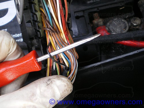
Feeding wires through the grommets is (I find) easiest done with a length of wire coat hanger, cut at an angle to make it sharp, with the relevant wiring taped firmly to the other end.
With the inlet manifold back in place, the rest of the LPG connections (electrical will be covered later) can be made. The schematic diagram supplied with the kit (or downloaded from the website) is very good and clearly shows the connections that need making. The Vacuum connections are actually the ones which require the most thought, IMO, but are fairly simple to work out. Unfortunately I don't have any pictures of these in situ.
The vapour feed that you took from the vaporiser and left loose needs to go to the LPG filter. This is a service item and should be positioned with this in mind as you will need to access it to change it.
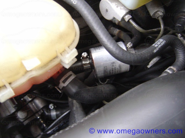
Then, from the filter it goes into the LPG measurement Tee
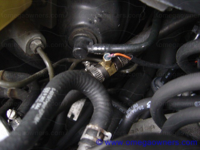
And from there it will go into the injector rail. At this point it is best to route the pipe (but not cut it and fit the injectors) and leave it until the throttle bodies are re-fitted, which can now be done, torquing the relevant bolts to the correct values. Temporarily fit the air intake pipe to the top and route it in the right direction to see how much space you have.
You can now see how much space remains for fitting the injectors. These should be mounted on the little rubber mounts supplied to reduce noise. Then make a/some brackets and mount them after connecting the injector pipes and cutting and fitting the vapour feed. In this picture we have mounted them to the cam cover using 2 of the bolts. The rear bracket is actually a little short and could do with being extended so that it completely covers the recessed hole to ensure it applies an even pressure. I don't think this has caused any leakage problems but you should really pack out the hole with some washers. These bolts should be torqued to the correct value.

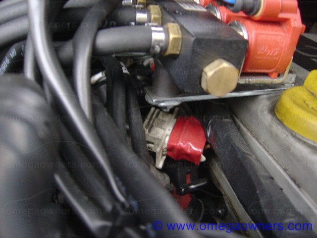
With the injectors in place you can now connect the correct plugs to them, ensuring that the plug, petrol injectors, and injector pipes all correspond to the correct cylinders.
Remove the air intake pipe again for space as required and this can be re-fitted after all the wiring has been tidied up.
Now we make the connections to the car's ECU.
Make sure that the battery is disconnected before continuing!The connections are all covered in the
LPG Electrical Connections thread so I will pass over it but will supply some pictures!
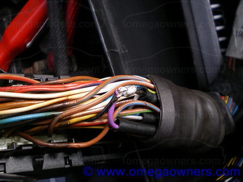
The wiring can be taken into the ECU box through the rubber grommet as can be seen in the last picture. Then it's just a case of locating the correct wires and making the connections.
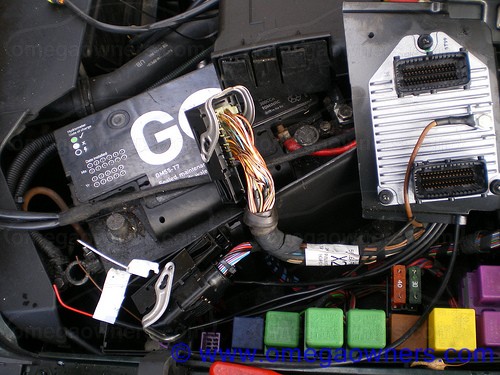

Apart from the extra wires there's very little evidence that any additional wiring has been done


 Author
Topic: Fitting LPG - 4 Cylinder Front End (Read 11316 times)
Author
Topic: Fitting LPG - 4 Cylinder Front End (Read 11316 times)